Use the station geometry
The mounting plane, its inclination and the working area define a geometric filter. The network sees the whole scan and receives the filter mask as context. Only points retained by the filter can be selected as part points.

No CAD file for the part? SI_Scan AI uses a neural network to recognise the part in a 3D scan and separate it from its fixtures, then reconstructs its surface. The result is geometry for SCAN2SPRAY and SI_Path, taken from the physical part.
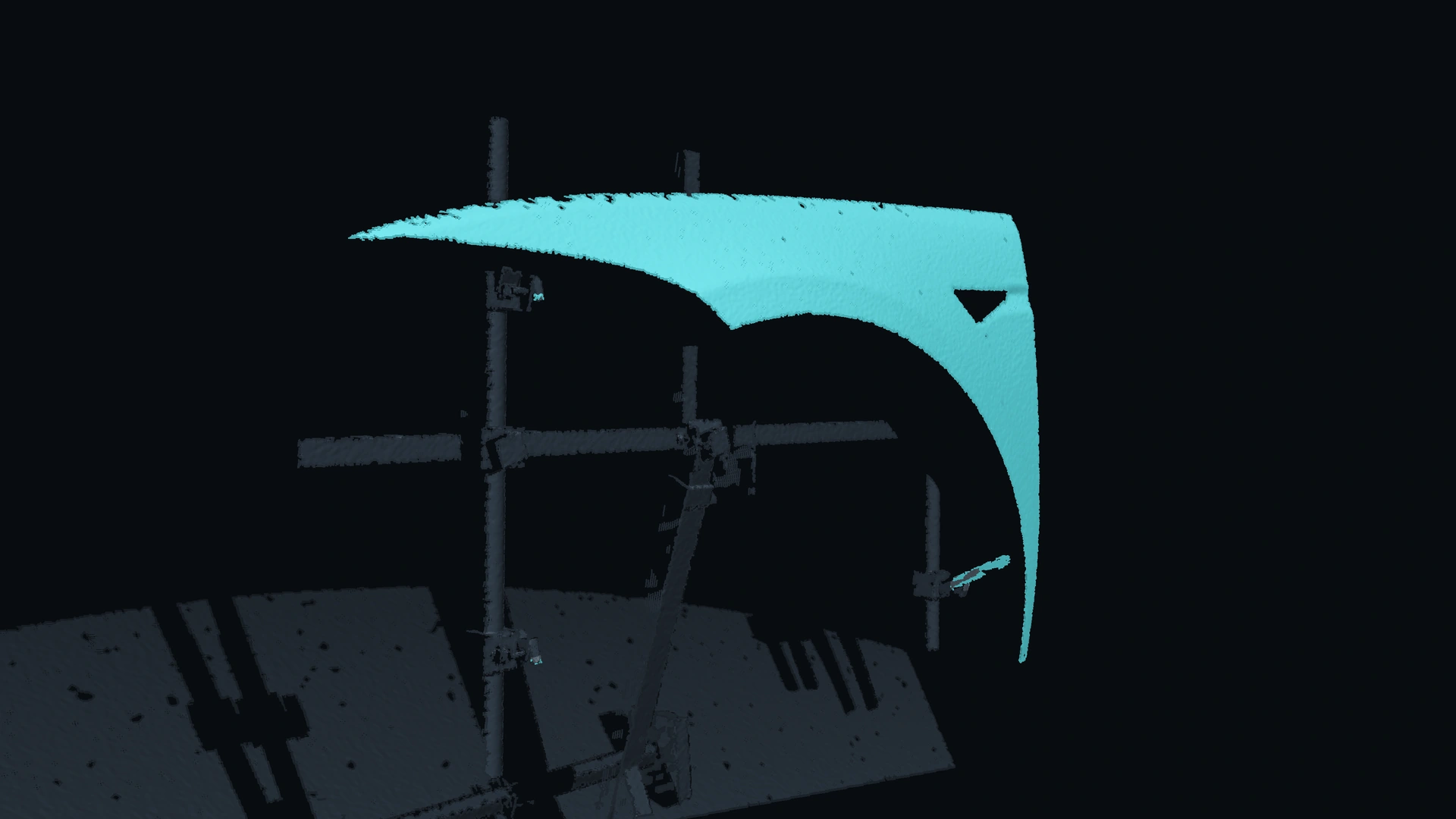




A scan of a workcell contains much more than the surface to be painted. We combine knowledge of the station with learned segmentation and geometric reconstruction, giving each stage a distinct task.
The mounting plane, its inclination and the working area define a geometric filter. The network sees the whole scan and receives the filter mask as context. Only points retained by the filter can be selected as part points.
The network assigns points to the part, fixture or background. This is particularly relevant where a rail, hook or clamp sits close to the part and cannot be separated by depth alone.
We build a triangle mesh from the selected scan points. Reconstruction addresses noise, isolated fragments and depth discontinuities while retaining the measured shape.
The completion stage is intended for incomplete edges and local gaps in the scan. Its task is to create a continuous surface for SI_Path while distinguishing measured geometry from inferred geometry and preserving intentional openings in the part.
A hook, rail or clamp can sit at the same depth as the surface to be painted. SI_Scan uses local shape and station context to distinguish the part from its fixture. The part surface forms the input for painting; surrounding structures retain a separate role in the workcell geometry.
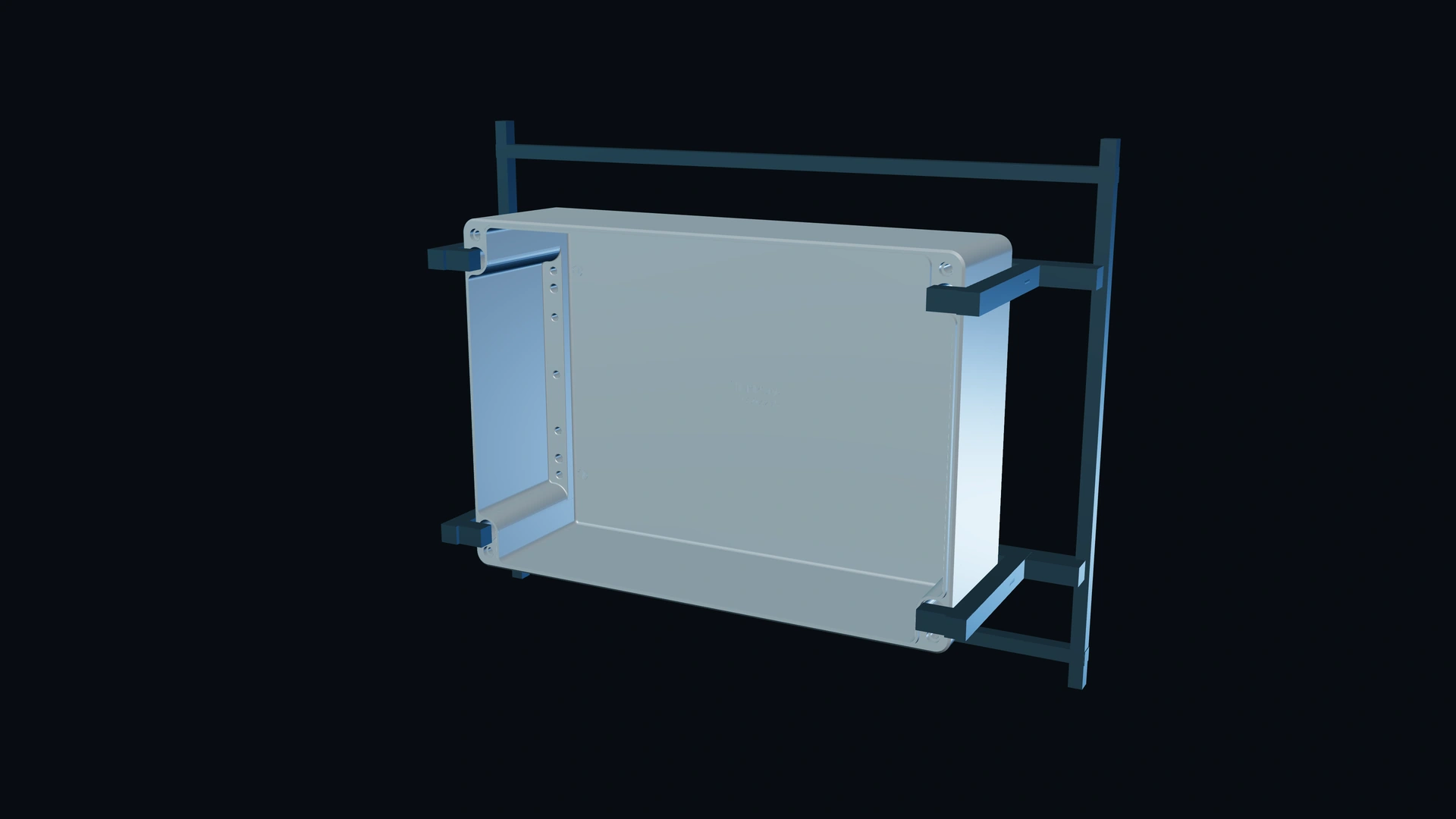
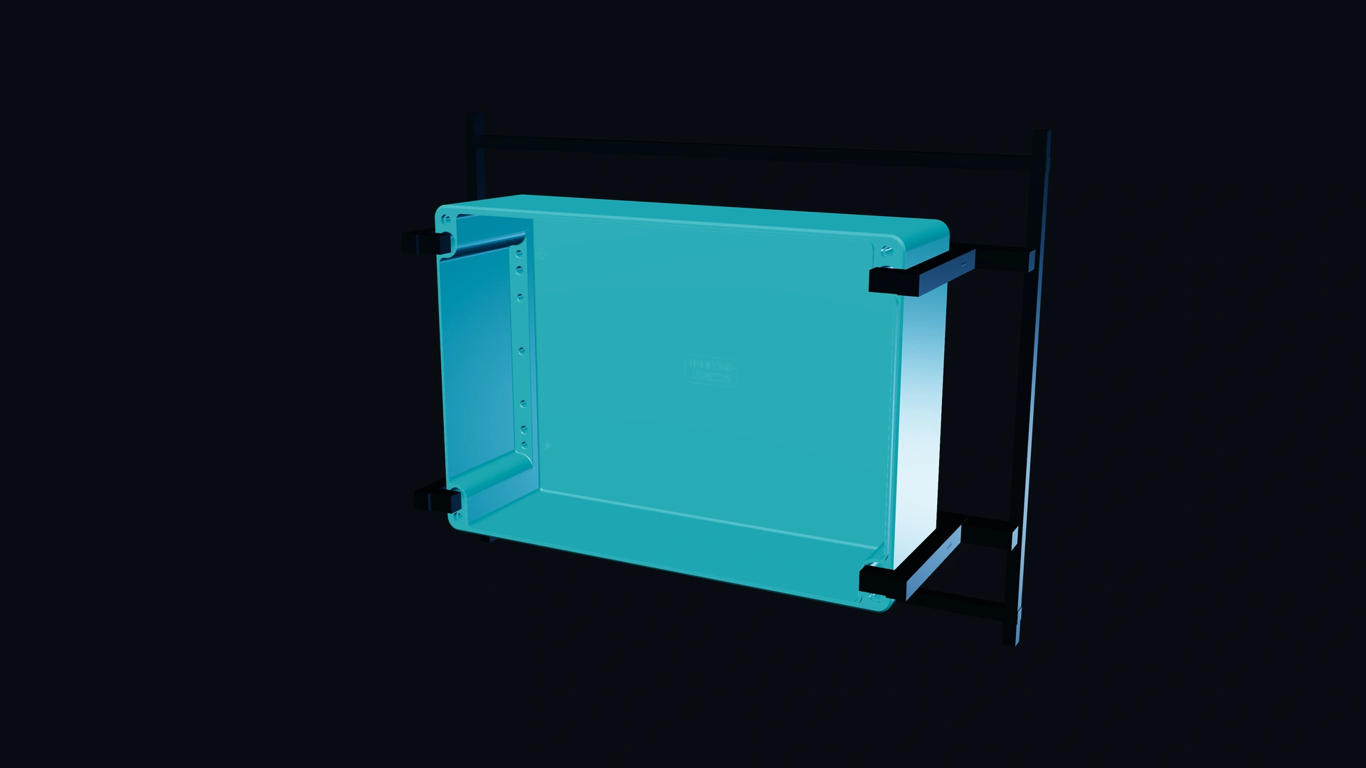
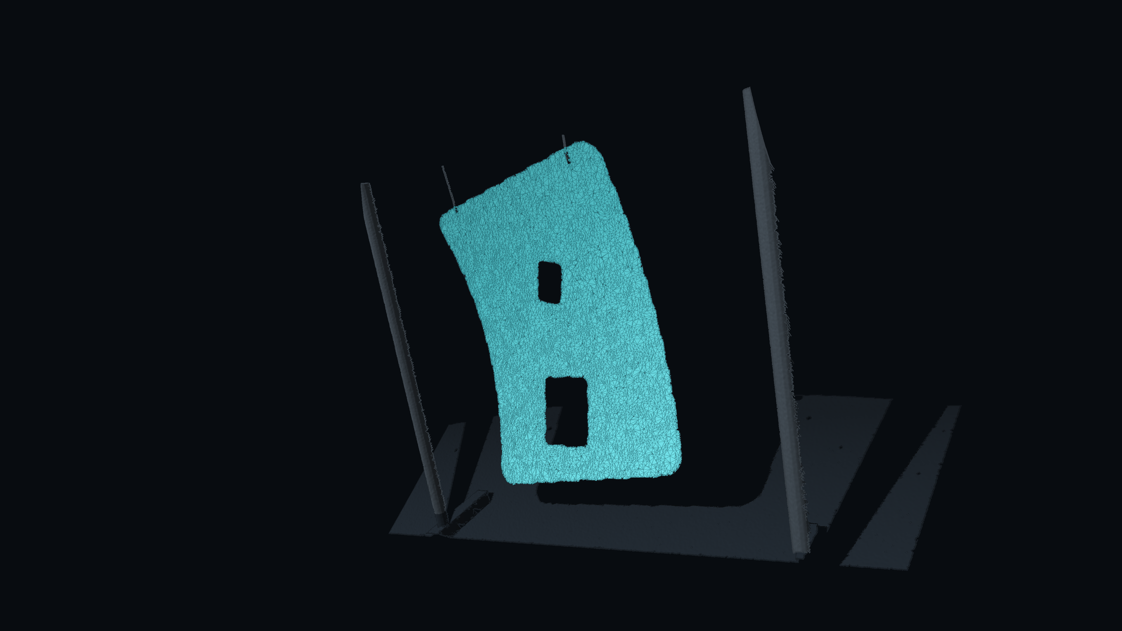
The neural network identifies part points; a separate geometry stage constructs the surface from those observations. The resulting mesh represents the surface visible in the scan, including the limits of what was measured.
Reconstruction must retain the distinction between observed and inferred regions, preserve narrow edges and avoid connecting unrelated surfaces across depth gaps. This information determines where the geometry can support path planning and where another observation is needed.
The data flow connects scene recognition, process planning and learned painting decisions. SI_Scan provides the geometric input: the part surface, its position and its relationship to the station. SCAN2SPRAY and SI_Path work from the same geometric reference.
Identify the part and reconstruct its observed surface.
Use the measured geometry in the workcell model and plan the painting process.
Use part geometry as input to learned painting decisions.
The interface specification pairs surface geometry with per-point class confidence, unobserved regions and references to the scan, calibration and model versions. Fixture geometry and unobserved space remain part of the workcell model for collision analysis, separate from the surface to be painted.
The network receives spatial feature maps arranged on the scan grid. These describe geometry relative to the station rather than the camera alone, so the known mounting configuration accompanies the measured surface.
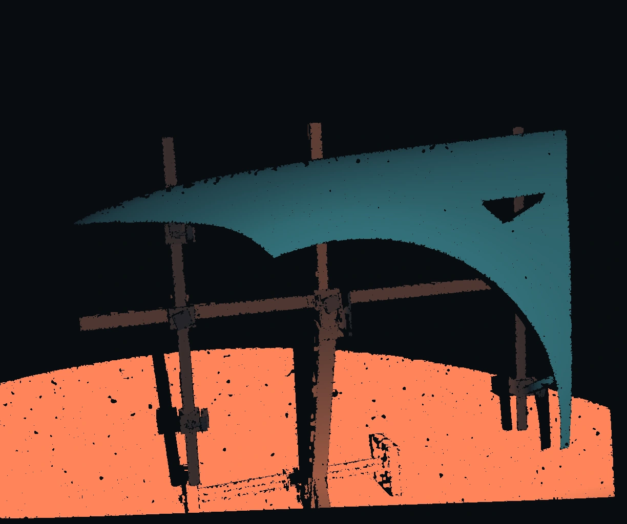
Distance from the mounting plane helps distinguish the part from structures behind it.
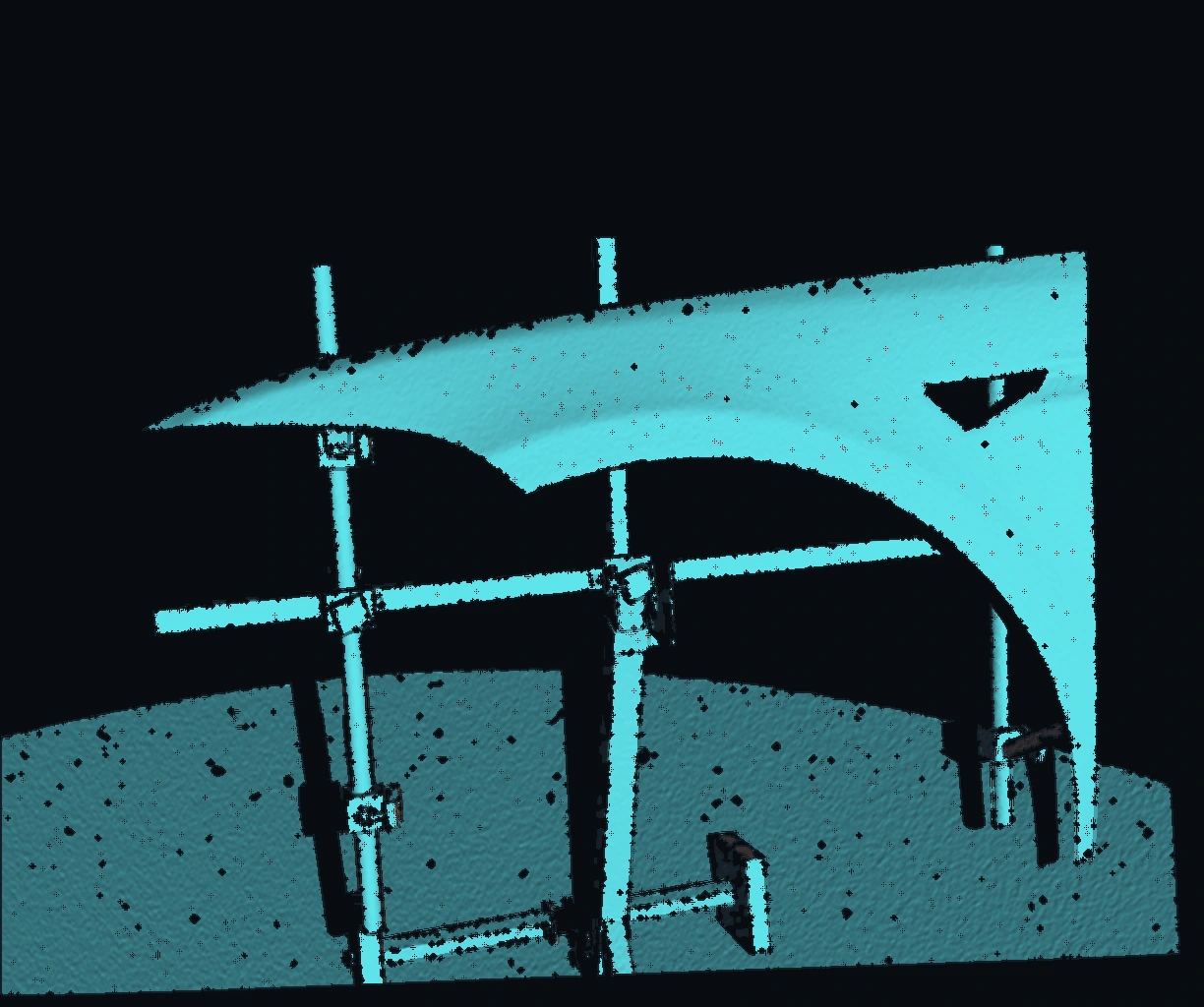
Local surface normals describe how the shape turns, bends and meets an edge.
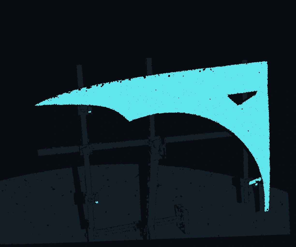
Position within the station and the geometric filter provide context for the network’s decision.
Our generator places parts in different mounting arrangements and simulates camera and projector visibility. Reference Zivid scans inform the camera model, noise and missing-point behaviour.
We include parts on rails, stand-off supports, hooks and clamps, together with stands defined by CAD. Variation helps expose cases where a simple geometric rule is insufficient.
We train the segmentation network in PyTorch using GPU acceleration. During inference, the trained model assigns scan points to scene classes. Data, model versions and evaluation settings remain tied to each experiment.
Test sets contain part geometries excluded from training. We assess retained part surface, unwanted fixture points and reconstructed geometry separately. Synthetic scenes provide labelled segmentation data; real reference scans support reconstruction checks.
Send us a part model or a sample scan and tell us how the part is held at your station. Together we define the application, adapt the test scenes to your station and evaluate the results against your geometric and process requirements.
contact@prismatec.app